
- Generic usb hub driver windows 7 32bit download how to#
- Generic usb hub driver windows 7 32bit download code#
- Generic usb hub driver windows 7 32bit download Bluetooth#
- Generic usb hub driver windows 7 32bit download plus#
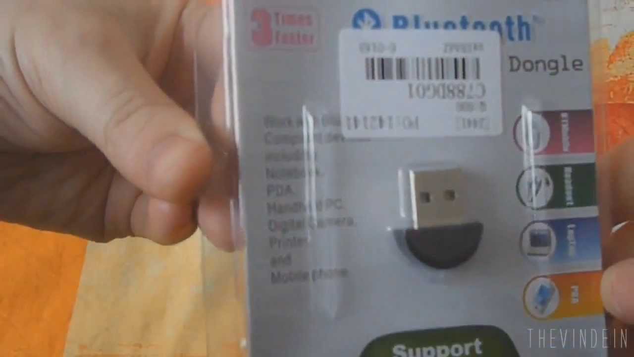
If you have an Intel based computer and are using the USB port for connecting your printer to your desktop, you could find that your printer isn't working with your Windows system any more.
Generic usb hub driver windows 7 32bit download code#
With the example code provided by AN65974, when FPGA reads data from FX3, a tap operation is required.How to Fix an Intel USB 2.0 Driver on Windows 7 May I ask whether this situation is normal.ĥ. The second use of the short data packet form (that is, when the last bit of data is 16384B, pull down the PKTEND signal), I can also see the correct result. First, the PKTEND signal can be raised all the way, and the commit can be made. When the FPGA writes to FX3, when the size of the data is 16KB, two tests are done.

When the FPGA writes to FX3, when the size of the data is 1024B, I tested two methods, one is in the form of short data packets, the other is by sending a zero-length data packet (ZLP), both methods can be passed I can see the correct data from the control center. Errors will occur, is there a requirement for the size of the data?ģ. I use short data packets to send 30B from FX3 to FPGA (when data is not a multiple of 4B). I would like to ask whether the smallest unit of data sent each time is 4B (32bit). Will FLAGA be pulled down from high every time I commit?Ģ.
Generic usb hub driver windows 7 32bit download plus#
When I write 1024B (the timing is to send 256 cycles of data plus a zero packet), the same phenomenon occurs. At this time, only 32B is written, and the buffer is definitely not full. Specifically, the size of a single buffer is 16KB. The FLAGA in the data sheet indicates the current state of the buffer (that is, whether the buffer is full, 0 means full, 1 means dissatisfaction), but when I send a short packet For example, at 32B (the timing is that slwr is pulled down for 32 cycles, and pktend is pulled down for one cycle), I can still see FLAGA from high to low (pulled down by about 11μs). FLAGA is configured as a dedicated thread flag Thread_0_DMA_Ready. The size of my upstream buffer is 4*16KB. The state machine is sync slave fifo state machineġ. The data bus bit width is 32 bits, and the watermark value is 6, I want to clarify, the configuration is as follows: Hello, I encountered some problems in the process of reading and writing FPGA and FX3.
Generic usb hub driver windows 7 32bit download Bluetooth#
Is what I am describing achievable with the AIROC Wi-Fi + Bluetooth Combos modules?
Generic usb hub driver windows 7 32bit download how to#
There doesn’t appear to be any documentation on how to access the WiFi and Bluetooth transceiver themselves to craft raw packets and send and receive them. This would allow use to filter out all ‘normal’ WiFi packets and focus only on our proprietary communication protocol. It would be very important if we could setup Rx filters that filters package that have a specific header pattern. We need to be able to select a channel on the 2.4GHz and 5GHz band, set the data rate and send and receive packets. This is because we have devised a very simple light weight proprietary communication protocol that is supposed to be very low power, simple and without requiring us to set up a WiFi network. Then we would like the WiFi module to go into transceiver mode to send and receive raw 802 WiFi packages. We have an IoT application which requires the use of the AIROC Wi-Fi + Bluetooth Combos modules, to go into AP mode with HTML server and host a user setting webpage. I imagine I'm missing some subtle issue with the Keil DP8051 compiler and some missing directive. There is no issue and no need for the CyDelay(1). I have an identical CySysTick routine in main.c on the PSoC5LP. If I uncomment the CyDelay(1), my toggling of the pin occurs every 300ms as intended. If((systick - systick_prev) >= VDAC_STEP_TIME) However, when I use the incremented variable and perform a simple operation (toggle a pin) every 300ms (=VDAC_STEP_TIME), it occurs every 5ms. I enter the user isr (via callback) once every 1ms as designed. In creating this CySysTick-compatible interface, I can create a CySysTick callback to a user isr. I'm creating a simplified version of the CySysTick API calls for PSoC3 that ONLY uses a single clock.

The DP8051 MCU on the PSoC3 doesn't not natively have SysTick timer resources which are available on the ARM MCUs. I'm currently trying to create a 'simple' version of the CySysTick functions for the PSoC3. However, I've spent most of my time with the PSoC5LP which uses the ARM GCC compiler. I'm an experienced embedded HW and SW designer. I've spent a few hours with multiple experiments and I'm ready to bang my head against a wall. If you're interested in finding the issue, I'd be thankful. I'm having an issue with creating a very simple program on the PSoC3. AIROC™ Wi-Fi and Wi-Fi Bluetooth Combos.


 0 kommentar(er)
